
DYNAMIC RESTRAINTS
Snubbers
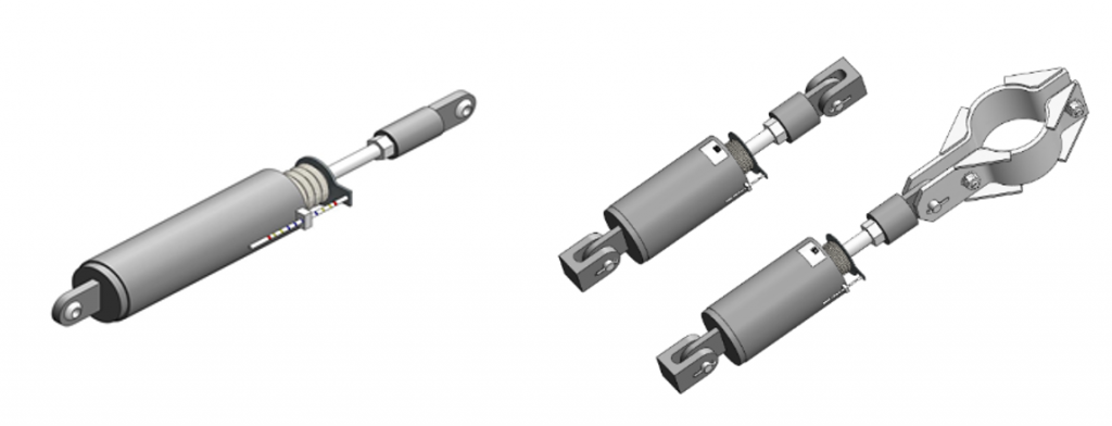
Dynamic Restraints commonly called Snubbers or Shock Absorbers are used to protect pipe work from abnormal movement in process piping in situations such as earthquake or fluid disturbance caused by valve closure or pumping.
The Dynamic Restraint is selected according to load, travel and likely environment conditions. Hydraulic Snubbers work using a principle similar to an automobile shock absorber where hydraulic fluid in a cylinder is displaced to another cylinder which is regulated with a spring loaded valve.
Assemblies
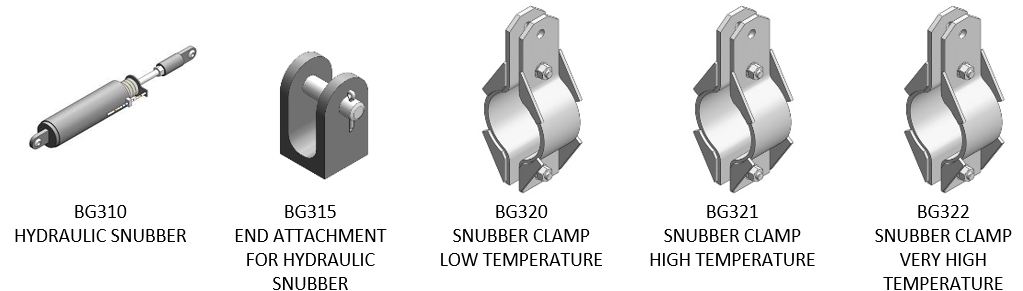
The Binder Snubber can be supplied as an assembly incorporating the specially designed Binder Pipe Clamps (BG320, BG321 & BG322) and BG315 End attachments.
The major advantages of the Binder Hydraulic Snubbers
- The oil reservoir is contained inside the cylinder casing of the Snubber to reduce the number of sealed connections thus eliminating the possibility of oil leakage.
- With the unique design of a built-in accumulator, the volume difference in the hydraulic chambers can be self-adjusted without any moving parts, thus significantly eliminating the possibility of mechanical problems and oil leakage.
- As part of the valve mechanism, a leakage plug is provided to release air bubbles generated from the fluid inside the hydraulic chamber by being effected by radiation or other environmental conditions. Any kind of hydraulic fluid can generate bubbles of air throughout the service period of the Snubber. Bubbles must be removed from the pressure chamber to maintain the required stiffness of the unit.
- Units are factory preset to the design stroke position, enabling the assembly to be installed without complex site work.
- High Durable metallic seals are used in the Snubbers.
- A colour coded stroke indicator provides easy in service inspection of the Snubbers
Design Characteristics
- Seals are durable against 1.5 times the inner pressure level.
- A spherical bearing is fitted to each end part of the Snubber assembly allowing a maximum of 15 degrees angular offset.
- Drag force (frictional resistance) throughout the overall stroke range is less than 2% of the rated load or 50kg, whichever is the greater at the input velocity of 1mm/sec.
- Bleed rate (release rate) under a lateral loading mode is 0.5mm/sec.
- The Snubbers can generate the required vibration control force between the input frequency range of 1 Hz to 33Hz.
- Snubber units are designed for a minimum expected life of 20,000 cycles.
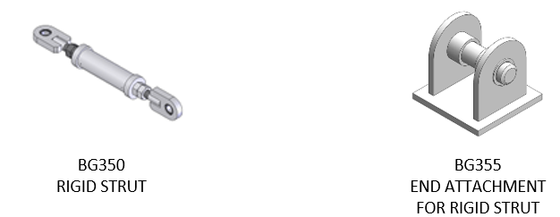
Introduction Rigid Struts
Rigid Struts are a rigid connection between a piping system and supporting structure. They offer a pivot connection, allowing a small angular displacement (+/- 7 degrees) whilst maintaining a rigid connection in both compression and tension. This allows a pipe movement due to thermal expansion in singular direction.
Construction
Rigid Struts are manufactured from thick walled pipe with threaded end connection plates welded to the pipe in left and right handed threads to facilitate installation.
End Connections
The end connections are fitted with captive, self-aligning spherical bearings to allow some angular displacement (+/- 7°) and connection to Binder pipe clamps and BG355 End attachments.
Accurately machined load pins as supplied with BG355 end attachments should be used to prevent vibration.
Right and left hand threaded shafts provide the facility for on-site installation and adjustment to the operational length.
Load Capacity
Compressive and Tensile loads up to 60,000 kg can be accommodated within the standard design range.
Strut Length
Rigid Struts are available from 550mm to 3000mm in length (load Pin centres). With an allowable site adjustment of +/- 75mm. Clients must nominate the desired load pin centre dimension ‘L’.
Finish
Standard Finish is HDG with Zinc plated end connectors.
Other Finishes are available on request.
Introduction Sway Brace
The sway brace is a device used to control pipe vibration and shock loads in a piping system. Vibration is controlled by exerting an equal and opposite force to that which caused the movement, returning the pipe to its normal operating position.
This is accomplished by using a spring coil of an appropriate spring rate that is connected to the pipe via a rod and turnbuckle assembly as shown in the image below.
Because of its design using a factory pre-adjusted single coil, the unit allows for +/- 75mm movement along the axis.
Please refer to detailed Product Catalogue available here.